WALLER CREEK DORMITORY
The University of Texas at Austin
Austin, USA
09 | 2018
Background
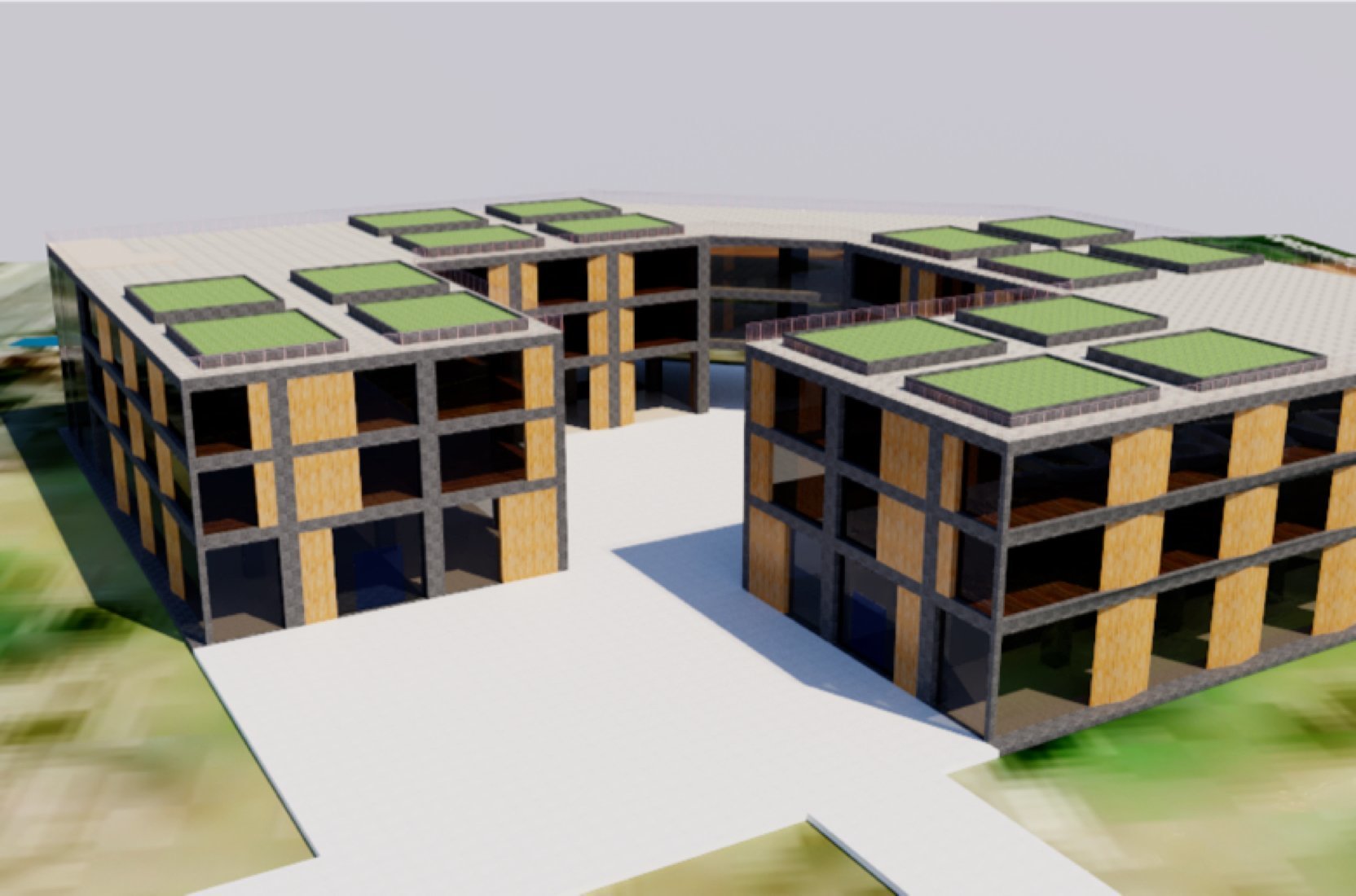
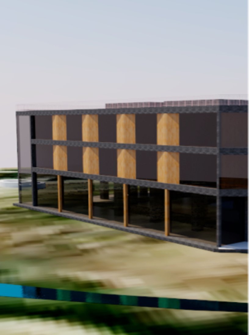
Our group (TEK40) was tasked with the project to design a new dormitory for 250+ students at the University of Texas at Austin campus. To achieve this goal, we planned the development of new infrastructure and modification of existing infrastructure in adherence with the guidelines found in the UT Campus Master Plan.
Logo Design
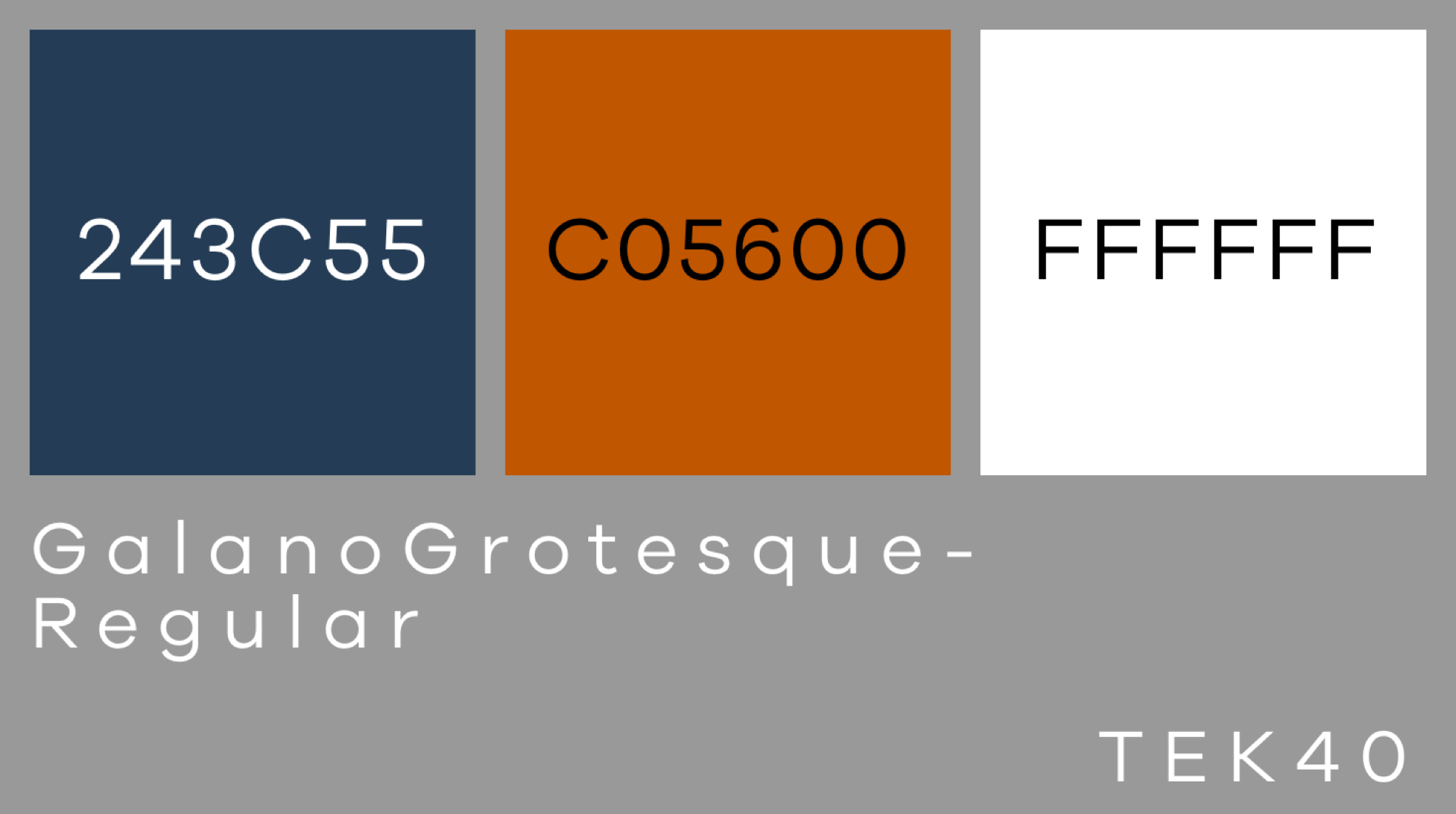
Before initiating engineering work, it was necessary for us to create a logo that would represent our goal to develop modern, yet sustainable designs which closely integrate 21st century technology onto the “40 Acres” campus. Group brainstorming led to the fruition of TEK40’s logo which derives its form from a fountain pen and the “T” shape.

Site Analysis
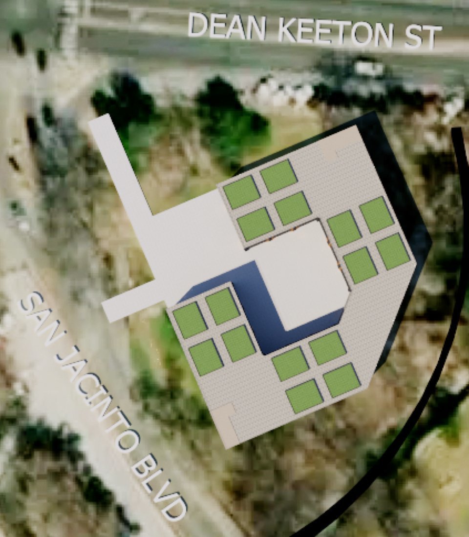
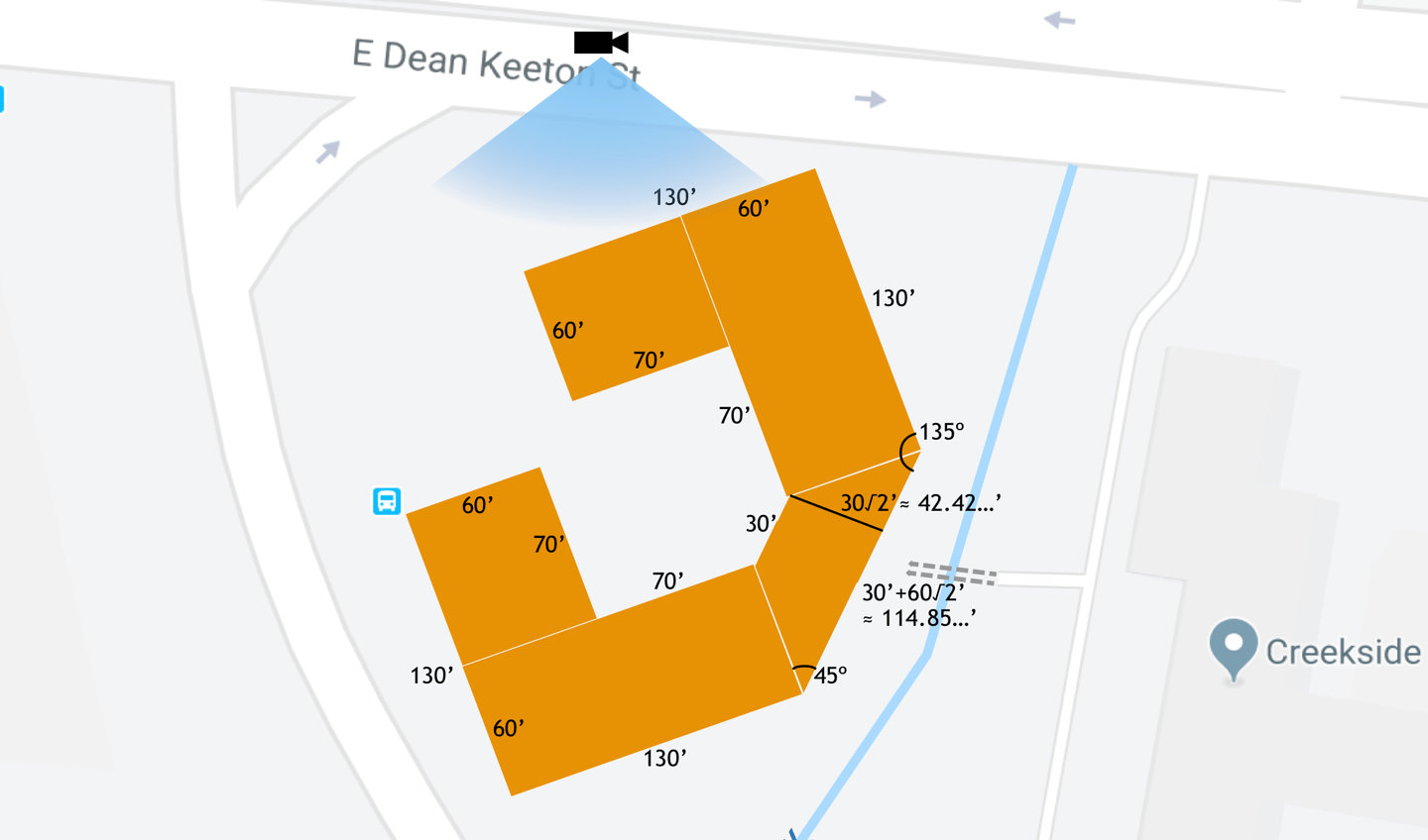
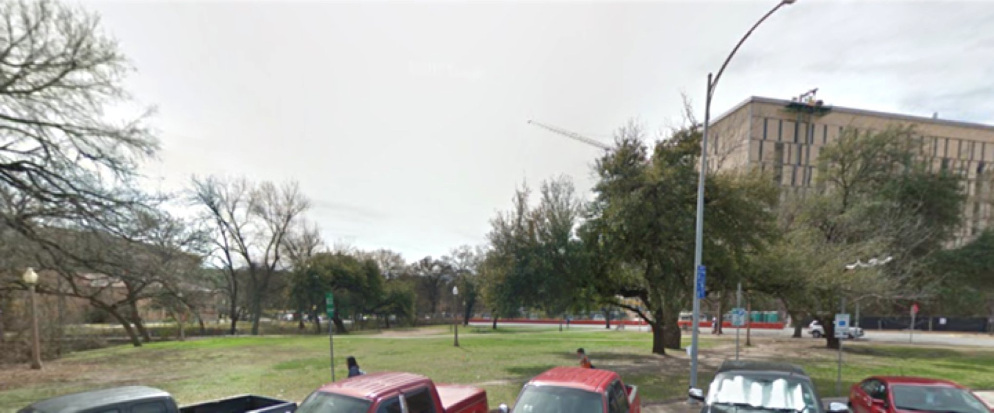
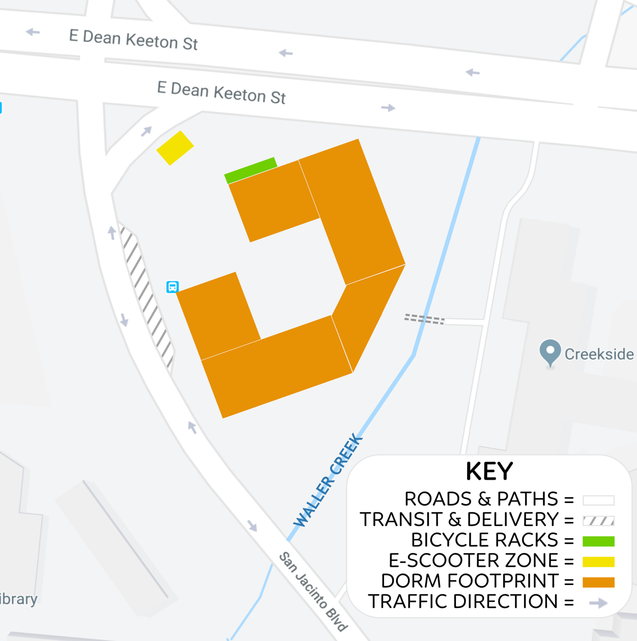
After creating our logo, we developed a series of plans based on tests at the site and its surrounding features. The relatively flat site includes an old sand volleyball court, scattered tables, light poles, a single bus stop on the western edge, and a bridge to the Creekside Dorm on the eastern edge of the site. The site’s perimeter is enclosed by Dean Keeton Street to the north, San Jacinto Boulevard to the southwest, and Waller Creek to the East.
Drainage Network
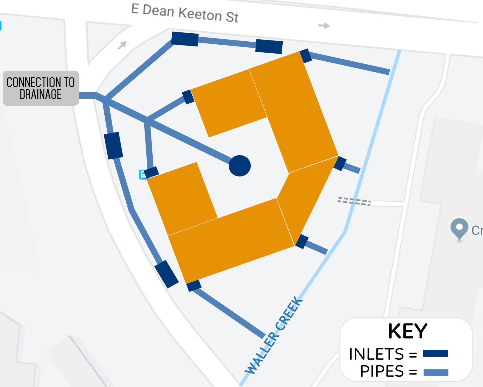
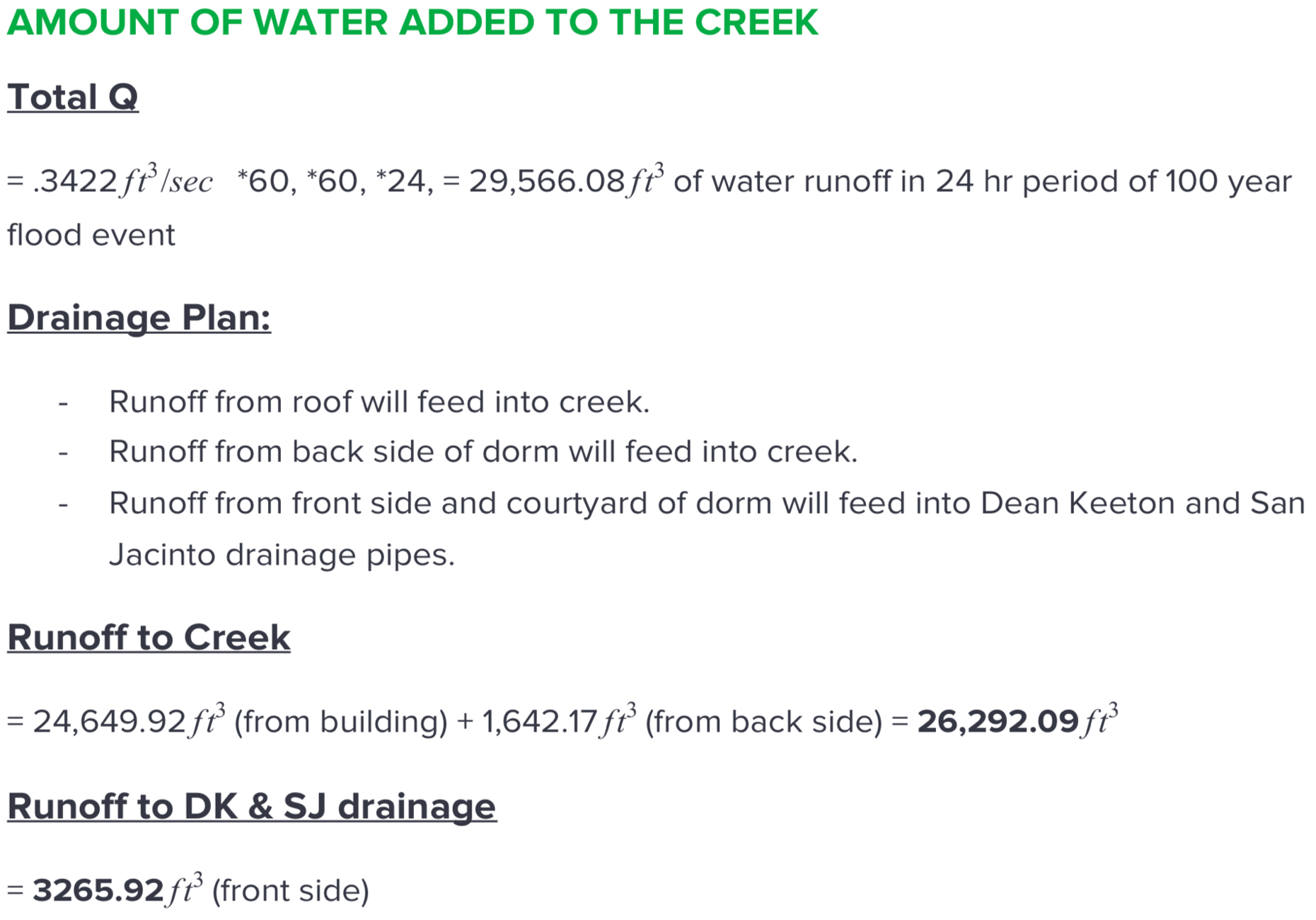
To account for a 100-year rain event, a gutter system is installed on the dorm roof. This will transport water water through a series of isolated pipes and underground inlets. Captured water is immediately reused on-site or drained into local reservoirs depending on building needs.
Signal Recalibration
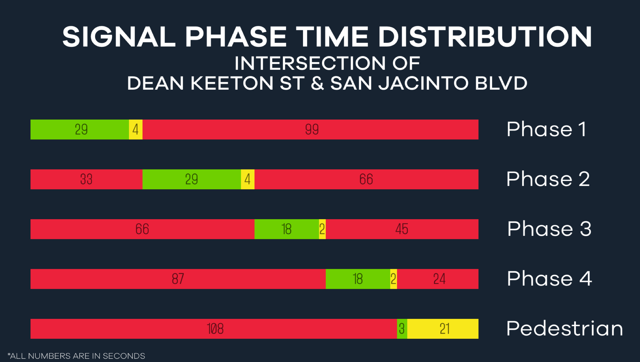
Since the Waller Creek Dorm will cause an increase in local foot, bike, and vehicle traffic, new steps will be taken to ensure traffic safety. Development of special zones adjacent to the dorm and retiming of the signal at Dean Keeton and San Jacinto safely enhance access and mobility to the site.
Column Design
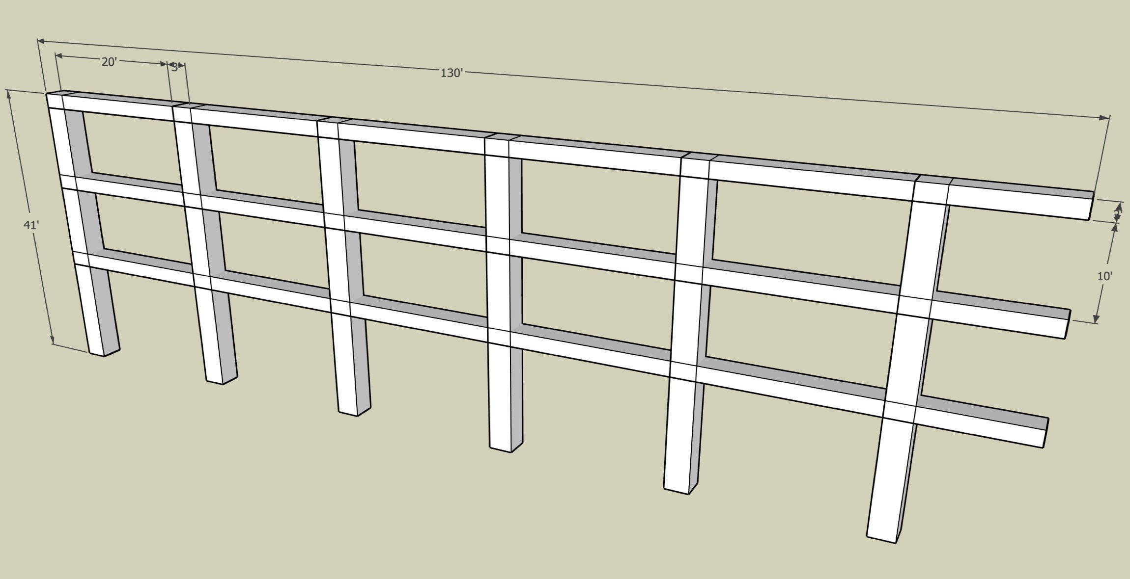
The proposed frame design accounts for all dead and live loads on the structure. Fixed joint concrete columns, measuring 3’x3’ and placed 12 to 20 feet apart, direct loads in the appropriate direction to maintain the building’s structural integrity.

Foundation
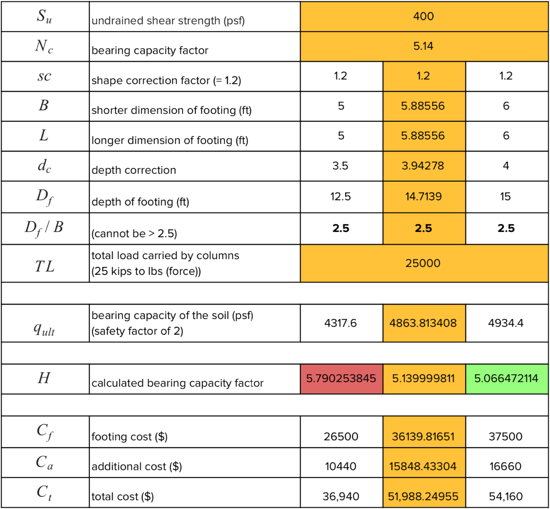
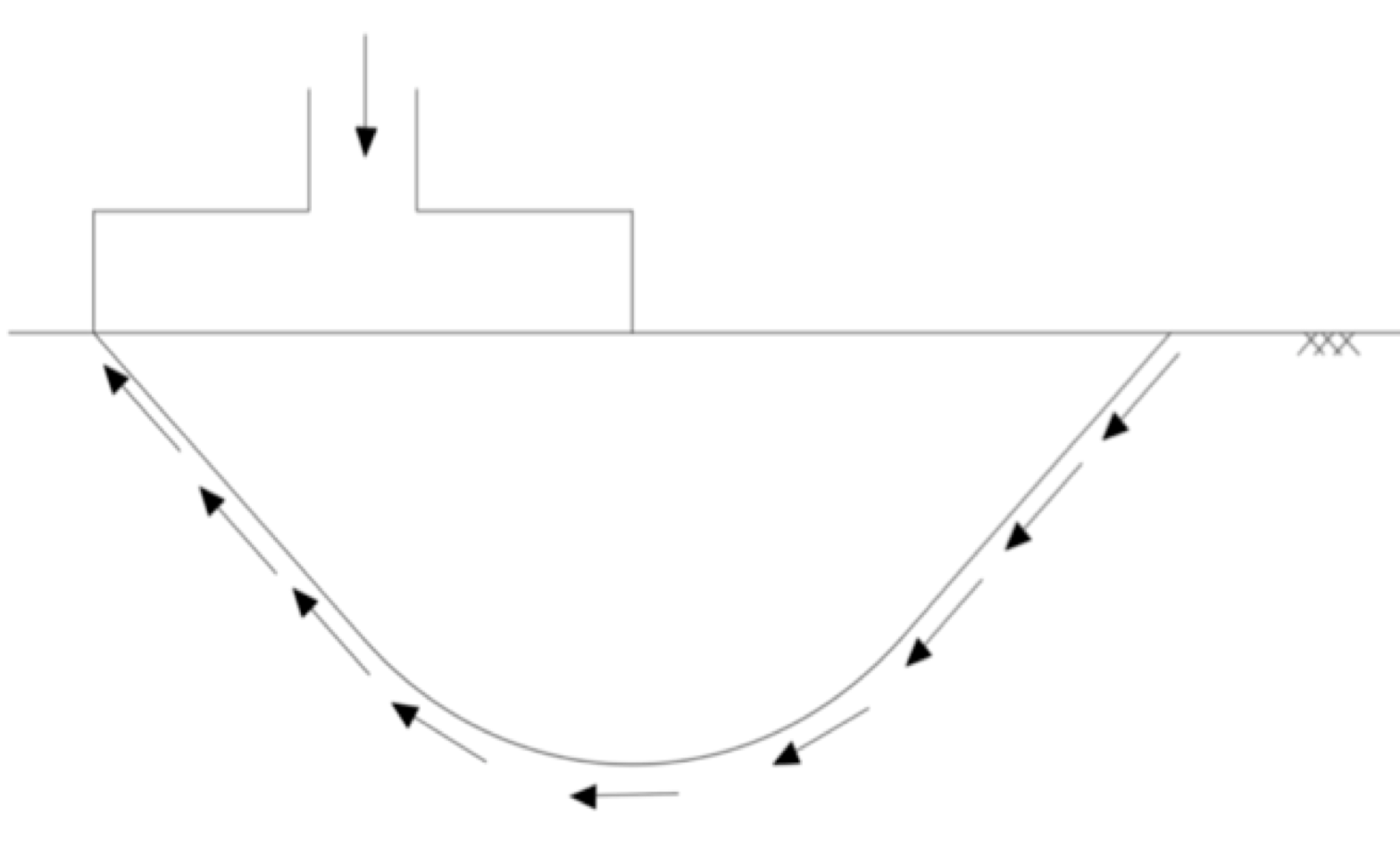
Footings of the optimized size and depth (calculated below) ensure that each column can safely sustain a total load of 25 kips (25,000 lbf). This plan minimizes the chances of general shear failure and prevents land depression caused by excess pressure on soil.
SEE FULL REPORT
